Journal - Reprogramming my Launchpad Mini
You can find updates on my progress regarding repairing/reprogramming my launchpad mini here.

Introduction
One day I got the idea to read out the serial data sent over USB by my launchpad with an arduino. I just thought it could be a cool way to use the launchpad as a controller, as it only sends and receives MIDI data. After a bunch of fiddling with open wires I crossed the wrong wires and bricked the device. A second-hand one would cost me about 50 euros. But why buy a new one when I can try to fix it myself?
Nov 2 2024 - Resoldering
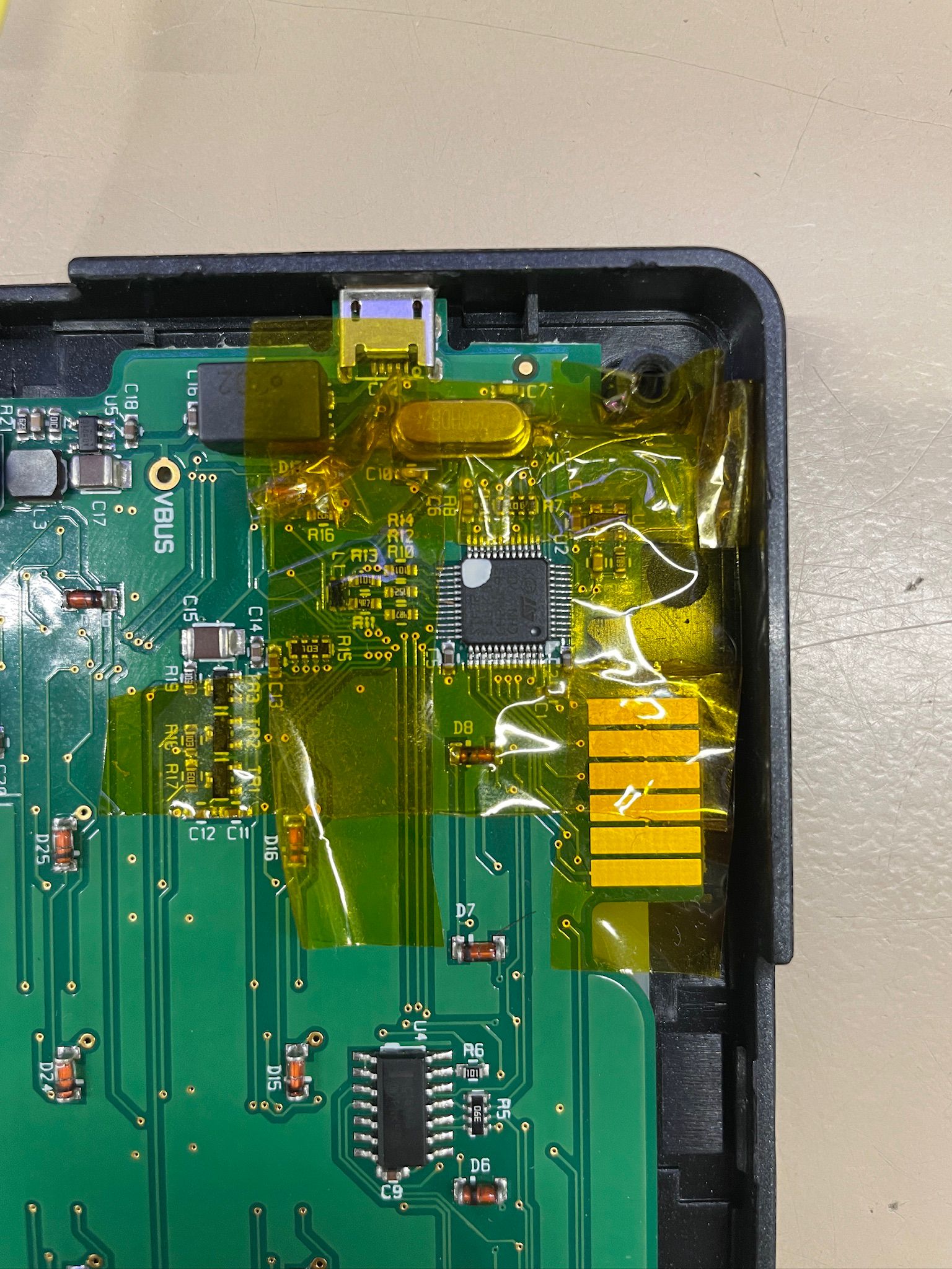
So today I bricked my launchpad. Seemed like the microcontroller was the problem. (spoiler, it wasn't)
Nov 9 2024 - Resoldering
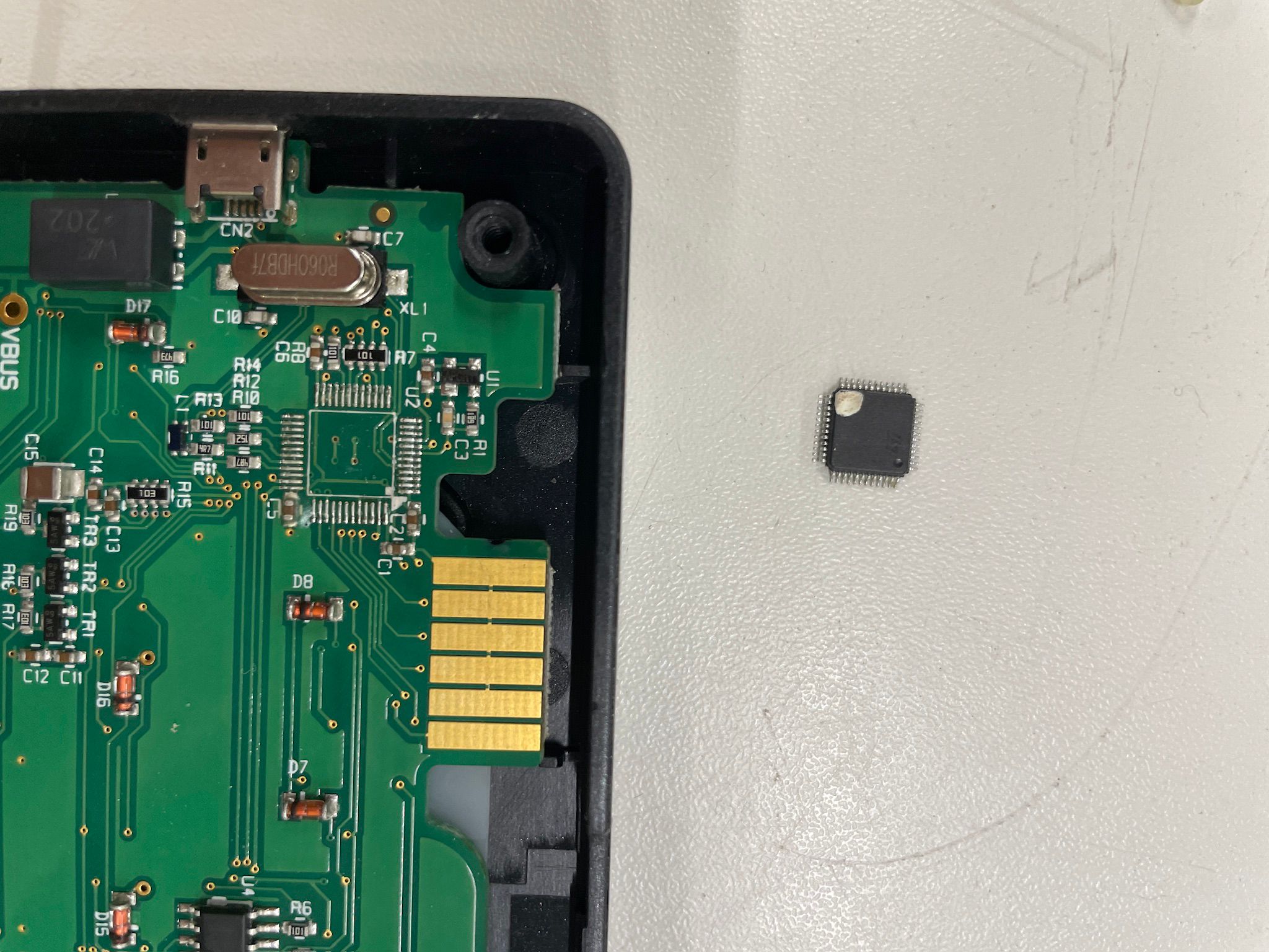
Some big progress! Today, with some help, I managed to replace the STM32 on the board with my new one from the blue pill board. Even after all this, though, no luck powering it. After some tests I discovered that the problem might've just been a voltage regulator I fried... That sucks. Next to that, I also lost the original controller, so I'm pretty much forced to reprogram it myself. (No, I'm not buying a new one) Next week I'll try and screw around with that.


Nov 23 2024 - Connectors
Not much progress today. I did a lot of research about JTAG connectors and STLink connections, and I'm still not sure whether I should get a JTAG programmer. They are quite expensive, and according to some people I should be able to program my board via STLink through the JTAG terminal if I wire it up correctly. I'll probably attempt to do that next week.
No luck with powering the board either.
Nov 30 2024 - Powering up
Some progress today! After some tests earlier this week, I realised that the broken voltage regulator shorted, which was why I couldn't hook up my STLink or power the board. Removing this voltage regulator allowed me to hook up my STLink and power the board properly. When I did so, some lights turn on, seemingly at random. After a while it seemed to "stabilize" into powering all LEDs. Somehow the components are receiving some signals that trigger the LEDs. I still cannot reach the STM though, whatever I try.
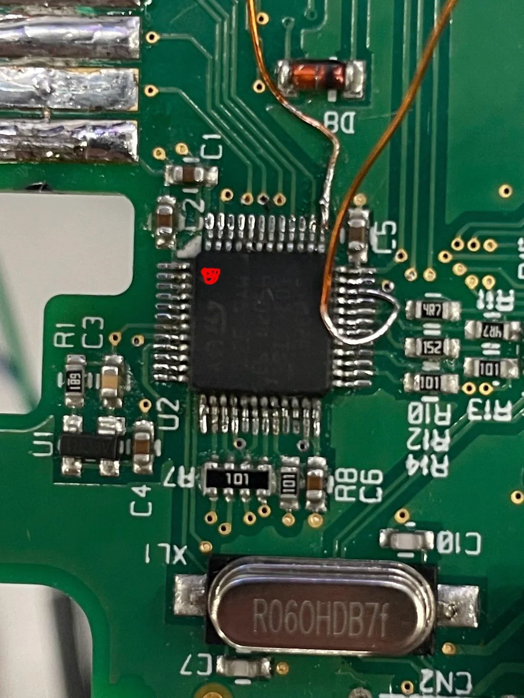
Something weird I noticed is that PA13 and PA14 are not actually connected to anything on the board, even though the datasheet does claim so. I painstakingly soldered some small wires onto those pins and hooked up my STLink pins directly to them. Still no results. Kind of afraid I fried it because of something I did earlier, whether it was trying to reach it with faulty wiring or overheating it due to the soldering.

Dec 7 2024 - Entering
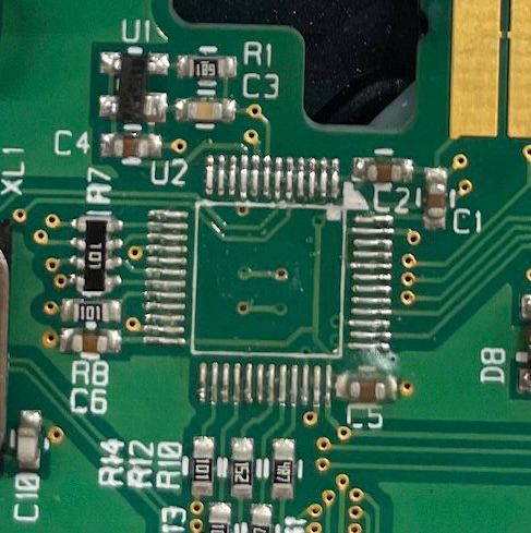
Some more progress today. Previous week I stated that the PA13 and PA14 pins weren't connected to anything, but I was wrong. I fished up an old picture where the MCU was desoldered and there were clear traces underneath it, which coincidentally connected to PA13, PA14 and some other pins. This means I can disconnect the very tiny wires I painstakingly soldered onto the MCU and just use the boards terminals to program it.

On top of that, I discovered that the backside's (relative to the MCU) JTAG terminal is actually not connected to the front sides. This clears up a lot about what it says on the datasheet, as I was really confused on how the JTAG terminal worked. When taking this into account, I can actually communicate with the microcontroller! There's some issues though, like not being able to erase or flash it, whatever I try. So that sucks.
After thinking about this, I think I'll just order fresh MCU's off AliExpress and see if I can replace the controller again soon.
Dec 21 2024 - Research
Earlier this week I received my microcontrollers from China! After removing the MCU all on my own and replacing it, I got it to connect to my computer again! It's fully functional and I can actually erase it and flash it, using the arduino IDE as well.
After inspecting the datasheet I know which pins to use to control the board, but I can't get anything to work yet. I'll look further into it next week.
Jan 4 2025 - Entering and breaking
Quite happy with my progress today! While trying to figure out why I couldn't get the board to work, I decided it'd be a good idea to hook the board up to an external power source instead of powering it only via the programmer. This is where I learned a valuable lesson, because the power supply was set to its highest settings and I fried the microcontroller. I spent a big part of the day replacing it again (I ordered 5 MCU's off ali) and finally got it to work again.
With the board all functional again, I deciced to continue working on the software. This is where I discovered a weird mistake on the datasheet, which is that the LED-controlling shift-registers pins for the clock and serial data-in were switched on the datasheet. No idea how that could happen. After correcting this in my software, I got it to work exactly as I expected.
TO-DO
- Implement LED control system
- Implement button press sensing
- Implement USB communication
- Find replacement for 3.6V voltage regulator (preferrably with same pinout)
- Implement USB bootloader for programming over USB?